5g FHD XLL 6 Axis EDM System
EDM Drill 3D Shaped Holes in Aerospace and Land Based Gas Turbine Blades and Components!
Our 6-Axis fast hole EDM XLL Drilling Machine provides precision 3D shaped hole burning capabilities, ideally suited for machining large, extra long, and heavy aerospace engine and land based gas turbine blades and components. With 36” of electrode capability, and an impressive 25” of Z Axis Travel, this user friendly machine offers a flexible, cost effective solution to your large turbine blade manufacturing needs. A robust, custom trunnion type tilt turn table with a stainless steel Erowa chuck allows for quick change over of part holding fixtures. The rotary axis are so configured to allow the work piece to be centered on both axis, reducing the distance traveled on the linear axis and increasing machine capacity and efficiency. The 5g Tek4 Tech-Pulse EDM Generator has can store up to 500 process parameter programs, with the ability to adjust the process parameter up to four times during the drilling of a single hole. A key feature of the Tech-Pulse Generator is its process analysis capability. The process is graphed showing a depth against time thumbprint, which allows the operators to easily develop new process parameters as necessary. This machine is enclosed in a custom designed internally illuminated machine enclosure with access via two horizontally sliding doors.Fast Hole EDM Drilling
Linear Stroke Specifications
-X Axis: 40.00”-Y Axis: 20.00”
-Z Axis: 25.00”
-A Axis: 360º (Rotary)
-B Axis: 360º +/-180º (Tilt)
-EDM Stroke: 36.00”
Machine Specifications
-Req’d Floor Space: 121'’×86'’-Max Work Envelope: 26”Ø×25”
-Max Part Weight: 250lbs
Accuracies:
-Linear:
20 µ (+/-.0004”) Accuracy
10 µ (+/-.0002”) Repeatability
-Rotary:
+/-25 arc seconds Accuracy
13 arc seconds Repeatability
Standard Key Features
-3D Shaped Hole Machining-Quick Change Guide & Electrode
-36” Electrode Length Capability
-Auto Tool and Guide Changer
-Process Finger Printing
-Fast Break Through
-Advanced Break Through and Pre-Break Through Detection
-Built in Heidenhain Probe
-5-Point Nest Probing System
-Deionized Dielectric Plant
Customization Options
-Auto Part Load and Unload-Crash Protection
-Laser Ablation
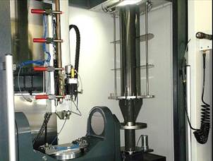
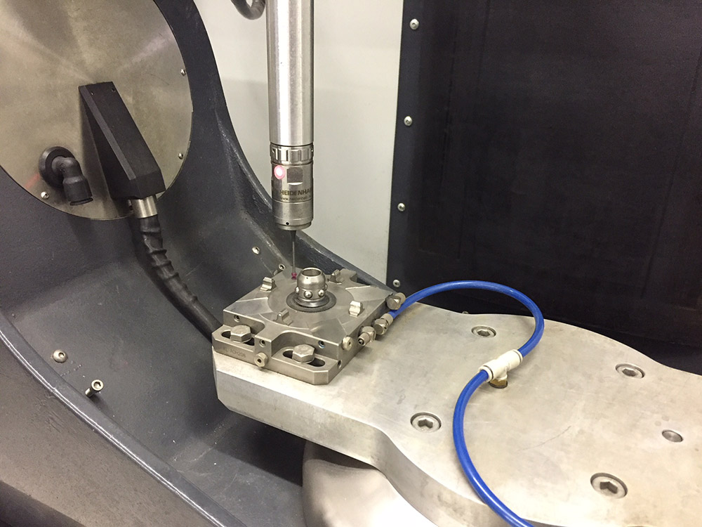
PROBING SYSTEM
The machine is fitted with a Heidenhain probing system. This is mounted on an automatically extending probe arm, which is activated by the CNC control. This probe is used in three main ways:1. Machine Check
A four minute CNC probe cycle checks out the accuracy of all 5 machine axis and also sets the zero datum points for all axis. This cycle enable the machine to be checked for geometrical accuracy on a daily basis and can be used to check for machine damage after a tooling crash.
2. Part Set
Built-in cycles in the control system enable the probe system to be used to “find” the Part. This is done using a 5-point probing routine (3+2-Plane-Line, 6th Point defined by the fixture). The advantages are:
- · Fixturing becomes lower cost
- · Multiple sets of datum’s can be used with re-fixturing
- · Parts cannot be miss loaded and machined
- · Improved Accuracy
3. Electrode Set
A special calibrated machined bore is probed and measured for position and diameter, each electrode tool as it is loaded is then “contact sensed IN” and the electrode is checked for diameter and position, an automatic tool offset is applied to the tool which compensates for any small positional error in the electrode position, this is especially useful when using long electrode guide holders.
Step 1: Check and Set the Machine
All axis are checked for positioning accuracy, datums are set and the part pallet chuck geometry is checked. This daily check ensures the machine can achieve maximum accuracy before being used.
Step 2: Electrode Position Set
The electrode position is now measured to the machine datum and tool offsets are automatically applied.
Step 3: Locate the Part Datums
The part is probed on its datums, “nested” by the software and then rechecked by the probe. Multiple datum’s can be used within one operation. For example, when multiple aerofoil offsets need to be applied.
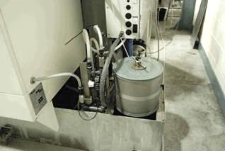
Dielectric System
The dielectric system is housed in a stainless steel tank unit located under and to the rear of the machine. The system is a two tank system, with a clean and a dirty tank. A pump continually pumps fluid from the dirty tank through a high capacity filter (used on EDM wire cut machines), when the clean tank is full it can weir over back into the dirty tank. The system has the capability to pass the fluid through an ion exchange resin bed canister to deionize the water; this is controlled by a valve system which is also controlled by a resistivity sensor so that a controlled value of resistivity can be maintained.A high pressure pump delivers fluid at a programmed pressure to the EDM electrode through the rotary spindle unit.
A heat exchanger with fitting ready for a connection to a chilled water supply or a free standing chiller unit (not supplied) is included with the system.
Tank Capacity is 55 Gallons (250L)
System on our FHD-5 Model
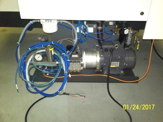
High Pressure Pump
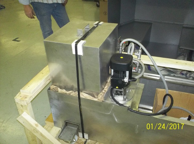
5gS FHD EDM XLL Dielectric System
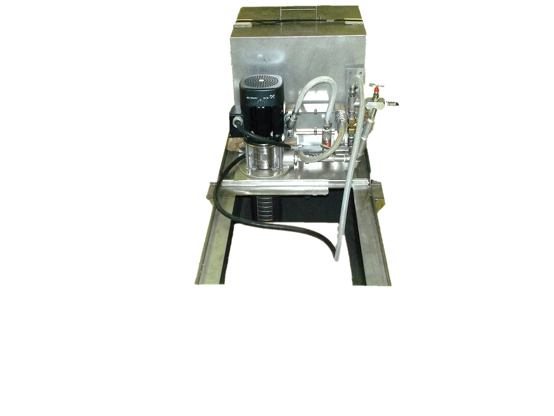
5gS FHD EDM XLL Dielectric System